Rexroth External Gear Pump and Internal Gear Pump
Description
Reviews
Download:
Rexroth External Gear Pump AZPF Description
It is the central task of external gear pumps to convert mechanical energy (torque and speed) into hydraulic energy (flow and pressure). To reduce heat losses, Rexroth’s external gear units offer very high efficiencies. They are realized by pressure-dependent gap sealing and highly precise production technology.
Rexroth external gear pumps are built in four frame sizes: Platform B, F, N and G. Within each platform different displacements can be realized by different gear widths. The pumps are available in the versions Standard, High-Performance, SILENCE und SILENCE PLUS. Further configuration variants are given by different flanges, shafts, valve arrangements and multiple pump combinations.
Construction
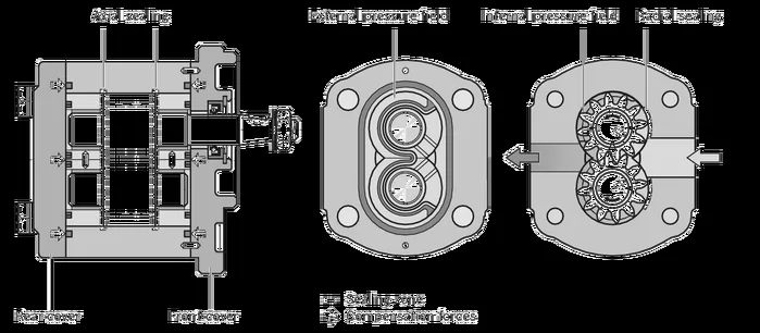
The external gear pump consists essentially of a pair of gear wheels supported in bearing bushes and the housing with a front and a rear cover.
The drive shaft protrudes from the front cover where it is usually sealed by the shaft seal ring. The bearing forces are absorbed by slide bearings. These are designed for high pressures and have excellent dry-running qualities, especially at low rotational speeds. The gear wheels have 12 teeth. This keeps both flow pulsation and noise emission to a minimum.
The internal sealing of the pressure chambers is achieved by operating pressure-dependent forces. This ensures optimum efficiency. On the outer face, the movable bearing bushes are pressurized with operating pressure and pressed as seals against the gear wheels. Special seals form the boundary of the pressurized zone. The radial sealing at the tips of the gear teeth against the case is provided by smallest possible gaps that are formed pressure-dependent between the gear wheels and the housing.
Assembly external gear pump
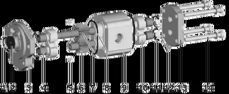
|
1 |
Snap ring |
8 |
Housing seal ring |
|
2 |
Shaft seal |
9 |
Pump housing |
|
3 |
Front cover |
10 |
Bearing bushing |
|
4 |
Slide bearings |
11 |
Axial field seal |
|
5 |
Centering pin |
12 |
Supporting element |
|
6 |
Gear wheel |
13 |
Rear cover |
|
7 |
Drive shaft |
14 |
Torx screws |
Gear pumps with integrated valves
In order to reduce piping complexity, a flow control valve or pressure-relief valve can be integrated in the cover of the gear pump. Such solutions are used, for instance, for the hydraulic oil supply of power steering systems. The pump delivers a constant flow irrespective of the rotational speed. The residual flow is either returned internally to the suction port or distributed externally to other consumers.
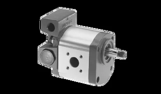
3-way flow control valve, residual flow returned in suction line
qconst = 2 to 30 l/min
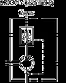
3-way flow control valve, residual flow distributed externally; loadable
qconst = 2 to 30 l/min
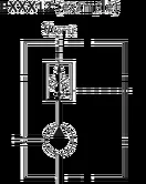
3-way flow control valve with pressure relief valve, residual flow returned in suction line
qconst = 2 to 30 l/min; p1 = 100 to 180 bar
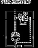
Pressure relief valve, pressure guide in suction line
p1 = 5 to 250 bar
Rexroth Internal Gear Pump, Fixed Displacement PGH-3X Description
Hydraulic pumps of type PGH.-3X are gap-compensated internal gear pumps with constant displacement.
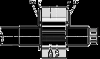
They basically comprise of: Mounting flange (1), housing (2), cover with through-drive (3), pinion shaft (4), internal gear (5), plain bearings (6), axial washers (7) and stop pin (8) as well as the radial compensation consisting of segment (9), segment support (10) and the seal rolls (11).
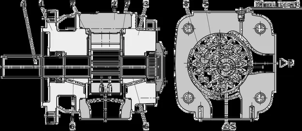
Suction and displacement procedure
The hydrodynamically mounted pinion shaft (4) drives the internally geared internal gear (5) in the direction of rotation shown.
The tooth clearances opening in the suction range suck in the fluid. The fluid is transported into the tooth clearances of pinion and internal gear, from the suction range (S) into the pressure range (P).
There, the fluid is displaced from the closing tooth clearances and delivered into the pressure port (P).
Suction and pressure range are separated by the radial compensation elements (9 to 11) and the tooth engagement between internal gear and pinion shaft.
Axial compensation
The displacement area in the pressure range is axially sealed by axial washers (7).
To the sides of the axial washers facing away from the displacement area a pressure field (12) is applied. These fields balance the axial washers vis-à-vis the displacement area, which results in a perfect sealing with low mechanical losses.
Radial compensation
The radial compensation elements consist of segment (9), segment support (10) and seal rolls (11).
Segment (9) and segment support (10) are arranged in the pressure field so that the resulting compressive force is basically accepted by the stop pin.
A small compressive force component presses segment and segment support onto the tooth tips of pinion shaft and internal gear and in this way provides for the sealing of the pressure range to the suction range with automatic clearance adjustment.
This is the prerequisite for constantly high volumetric efficiency during the entire operating time.
The clearance adjustment of segment and segment support is made possible by the seal rolls located inbetween.
Hydrodynamic and hydrostatic mounting
The pinion shaft (4) is accepted by hydrodynamically lubricated radial plain bearings (6).
The internal gear (5) is mounted hydrostatically in the housing.
Gear tooth system
The gear tooth system with involute edges has a large meshing length for little flow and pressure pulsation and thus guarantees low-noise running.

PGH-type hydraulic pumps are gap-compensated internal gear pumps with fixed displacement. The hydrodynamically mounted pinion shaft drives the internal gear. The pinion shaft and internal gear tooth clearances opening in the suction range suck in the hydraulic fluid and transport it to the pressure range. The suction and pressure range are separated by the radial compensation elements and the tooth engagement between the internal gear and pinion shaft.
HEASH TECH’s supply is equal to your demand. Rexroth original and new external gear pump AZPB, AZPF, AZPN, AZPG, AZPS, AZPT, AZPU, AZPJ, Rexroth 0510 gear pump, 0518 gear pump, 0511 gear motor and Rexroth Internal gear pumps PGF, PGH-2X, PGH-3X, PGH-4X, PGM-4X.
Rexroth External Gear Pump Technique Data
Safety requirements pertaining to the whole systems are to be observed.
▪
Please contact us for applications with frequent load changes.
▪
Pressure definition

|
|
p1: Continuous pressure max. |
|
|
p2: Intermittent pressure max. |
|
|
p3: Pressure peaks max. |

Note
You can find diagrams for a rough calculation in chapter "Diagrams / Characteristic curves".
General technical data
Hydraulic fluids
The external gear unit is designed for operation with mineral oil according to DIN 51524, 1-3. Under higher load, however, Bosch Rexroth recommends at least HLP compliant with DIN 51524 Part 2.
Application instructions and requirements for hydraulic fluids should be taken from the following data sheets before the start of project planning:


